Basic Platforms

Platforms are raised planes that are above the spread. The simplest version is the Parallel Platform. Then there are Concave, Convex and Tilted versions; which pitch the Platform towards the gutter, away from the gutter, and out of parallel to the Spread along its width. All of the above versions have the center seam running parallel to the gutter. All can be designed in two varieties: "movable" and "fixed". Movable means that the platform can be pulled to the left and right when open. Fixed means that it is held rigid by triangulation.
On this page, the above simplest concepts are discussed. On the next page, "Platforms, Part B", five other complex designs are shown: Offset Fixed Parallel, Sloped, Compound, Multi-Layer, and Closed Ends.
IMPORTANT NOTE! Each example below has a lin diagram as well as photographs. The text in each line diagram uses certain letters to denote lengths, ect. This helps explain the relationships and differences in certain details. Don's confuse those letters to ther ones unsed in the photos accomanying descriptions. THere are lots of "x's, Y's, and Z's used in the photographs to denote gluing relationships only.
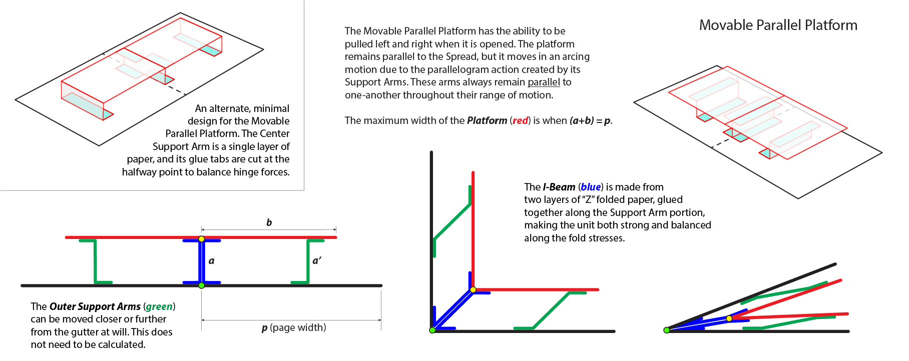
Movable Parallel Platform
.")
A Movable Parallel Platform is in essence a double-ended Parallel Scenery Flat, where the Center Support Arm acts like a leaf standing on end (see the page: "Spread Defined" for leaf description). The same rules of perpendicularity and parallelism apply to Movable Parallel Platforms as they do for Parallel Scenery Flats. All arms are parallel, and the same length as one-another. In the image, the arm length is (h).
This design is "movable" because the spread, platform, Center Support Arm, and Outer Support Arms create parallelograms that flex at their hinges.
In this example, the Center Support Arm is a single unit to ease installation, and is labeled with "X"s and "Y"s. The Center Support Arm is glued to both the Platform and the Spread as indicated. here are two Outer Support Arms labeled with "Z"s on them. The Out Support Arms get glued to the platform, and then are automatically aligned to the spread.
Special care needs to be taken to balance the forces of the folds in Movable Parallel Platforms. Paper folds have springiness, tending to naturally swing open somewhat. Because of this effect, if all folds are angled in the same direction, the platform will shift off center. To counteract the problem, the left Support Arm is shaped like a "Z" while the right Support Arm is shaped like a "Reverse Z".
Fixed Parallel Platform

 that once installed form a tent shape; a Platform marked with tab locations; and the Spread, marked with the first two tab locations. Notice that all four Support Arms are the same height (h).")
A Fixed Parallel Platform uses a Tent Fold to lock the platform in place, which happens because of the tent's triangular cross section. Although this Tent Fold is constructed from four planes, two of them are glued to the Spread, and they become co-planar when the Spread is fully opened, which forms the rigid base of the triangle.
An Even Tent Fold will cause the platform seam to run parallel and directly above the gutter.
Outer Support arms are added to raise the platform up, and parallel to the spread. There is only one proper length and pitch to the Outer Support Arms, relative to the Tent Fold. The length of the Support Arms must match the length of the Tent's riser, and it must be pitched parallel to the Tent riser. This will allow each side of the Fixed Parallel Platform to act as mirrored parallelograms, allowing the page to fold closed.
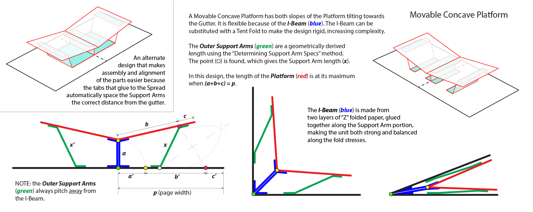
Movable Concave Platform
; half of the Center I-Beam structure (striped yellow), unique glue tabs that attach to the Spread, labeled (L1) and (L2); and the Outer Support Arms, labeled (h1) and (h2).")
 showing where to position the left and right support arms so that the platform is tilted to the desired angles and will also close flat.")
Concave Platforms run both sides down to the gutter. Both sides can be either identically mirrored or completely unique. In this example the left side is pitched steeper.
NOTE: both Outer Support Arms must slope outwards on Concave Platforms.
Notice that in this example, the length of line (bc) is the same as line (bd). This does not have to be the case: they can be different if desired. But since they are the same, the accumulated lengths of lines (ab)+(bc) = (ab)+(bd). Because of this, it can be seen in that the total lengths of both Combination Support Arm elements are the same. The difference is in the fold proportions, (L1:h1) and (L2:h2). Finally, because (bc)=(bd), (L1+h1) = (L2+h2).
The Support Arms (yellow lines with red dots) are not the same because the pitches of the platform are different. The longer the Support Arm has to be, the shorter it must be from the gutter (a).
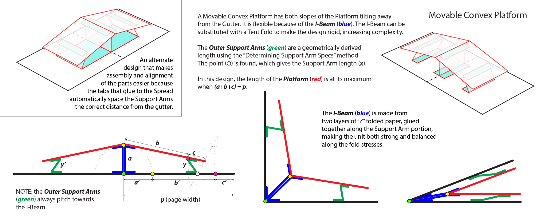
Movable Convex Platform
; half of the Center I-Beam structure (striped yellow), unique glue tabs that attach to the Spread, labeled (L1 ) and (L2); and the Outer Support Arms, labeled (h1) and (h2).")
 showing where to position the left and right support arms so that the platform is tilted to the desired angles and will also close flat.")
Both sides of Convex Platforms run away from the gutter. Both sides can be either identically mirrored or completely unique. In this example the left side drops quicker.
NOTE: both Outer Support Arms must slope inwards on Convex Platforms.
As in the Concave example described earlier, this Convex example has line (bc) = (bd). Of course, they can be different if desired. Just as with the Concave example, since they are the same, the accumulated lengths of lines (ab)+(bc) = (ab)+(bd). Again, it can be seen in that the total lengths of both Combination Support Arm elements are the same. The difference is in the fold proportions, (L1:h1) and (L2:h2). Because (bc)=(bd), (L1+h1) = (L2+h2).
The Support Arms (yellow lines) are not the same because the pitches of the platform halves are different. The longer the Support Arm has to be, the shorter it must be from the gutter (a).
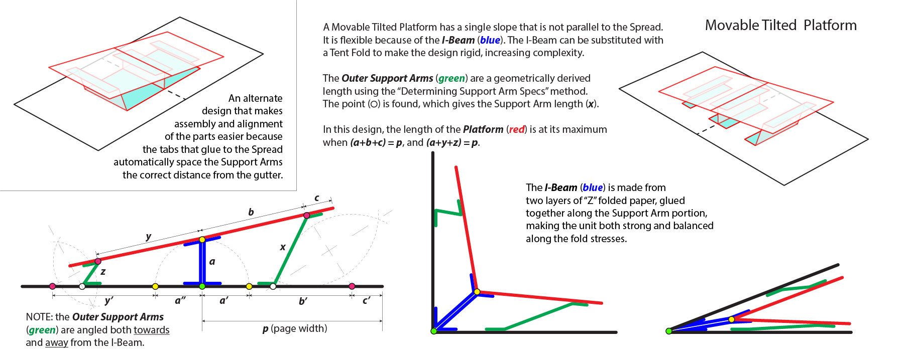
Movable Tilted Platform
; half of the Center I-Beam structure (striped yellow), unique glue tabs that attach to the Spread, labeled (L1 ) and (L2); and the Outer Support Arms, labeled (h1) and (h2).")
 showing where to position the left and right support arms so that the platform is tilted to the desired angles and will also close flat.")
Tilted Platforms have a continuous slope across both halves of the platform. They can tilt to the left or right of the gutter.
NOTE: the left Outer Support Arm slopes inwards and the right slopes outwards; sloping in the same direction, but at different pitches. The pitches are different because although their top ends are equidistant from point (b), their bottom ends are not equidistant from point (a). If you want the pitches to match, then the design would have to be derived in another way; where the bottom positions become equidistant from point (a), causing their top ends to no longer be equidistant from point (b).
As in the other two previous examples, (bc) = (bd), and as discussed earlier, this is not a requirement; they can be different. Any length that is required for aesthetic and structural reasons can be used.
Once again, since they are the same, the accumulated lengths of lines (ab)+(bc) = (ab)+(bd). The total lengths of both Combination Support Arm elements are the same. The difference is in the fold proportions, (L1:h1) and (L2:h2). Because (bc)=(bd), (L1+h1) = (L2+h2).
The Support Arms (yellow lines) are not the same because the left side pitches down from the gutter, and the right side pitches up from the gutter. As with all platform designs, the longer the Support Arm has to be, the shorter it must be from the gutter (a).
Supporting Videos
A 44-minute demonstration on assembling five basic Platforms. You may wish to play this video at 1.5x or 2x speed - that way you can speed past my errors faster!
A 2-1/2-minute video showing four Platform examples. The example in the Human Body book actually shows an advanced mechanism called an "Offset Fixed Parallel Platform", which will be described in "Platforms, Part B".